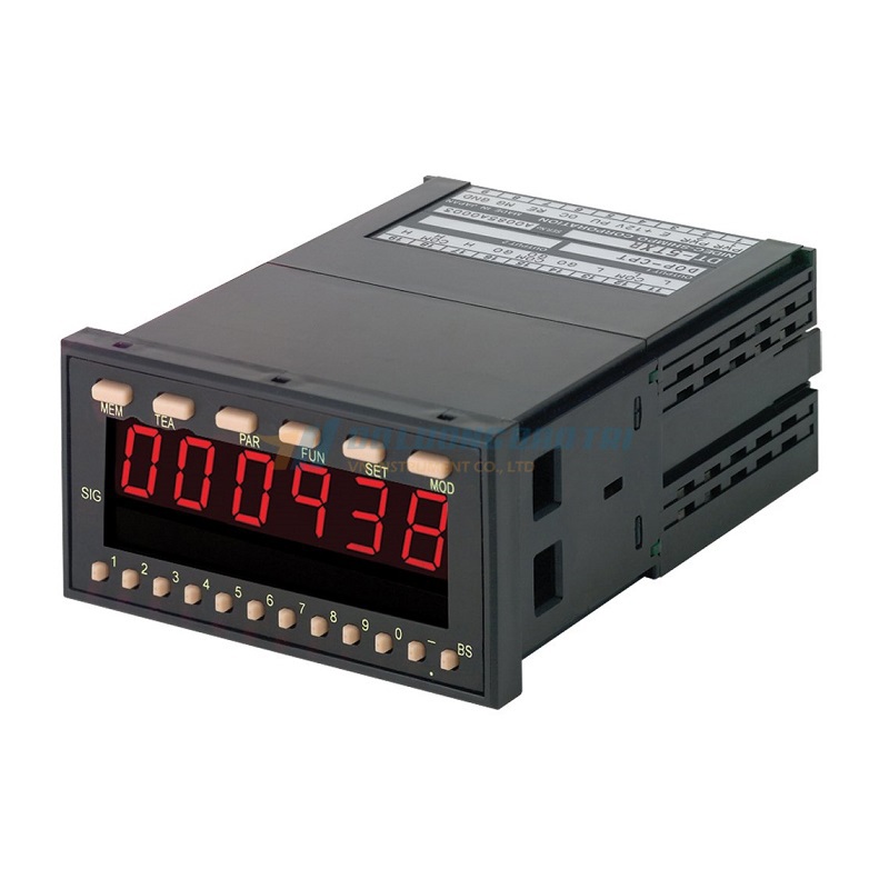
Bộ đo và giám sát tốc độ quay SHIMPO DT-5TXR 5TFR 5TVR
- Máy đo tốc độ vòng quay SHIMPO
- Thiết bị đo tốc độ vòng quay SHIMPO
- May do toc do vong quay
- Thiet bi do toc do quay
- Máy đo tốc độ quay động cơ
- Máy đo tốc độ quay cánh quạt
- Máy đo tốc độ quay kiểu tiếp
- Máy đo tốc độ vòng quay
- Bộ hiển thị tốc độ vòng quay
- Bộ đo và hiển thị tốc độ vòng quay
- Bộ đo và giám sát tốc độ quay
DT-5TXR/5TFR/5TVR Series High-Performance Tachometers
A high-performance panel-mount meter equipped with dual sub-indicators, having excellent waterproof properties (equivalent to IP66) and simple setting features. It accepts input signals from various devices such as rotary encoders, magnetic sensors, and line drivers, as well as analog input (basic input: DT-5TXR, differential input: DT-5TFR, voltage input: DT-5TVR). Provided with a memory function to store and indicate the maximum and minimum values.
Features
Provided with various functions including calibration, memory, and prescaling
The tachometer accepts input signals from various devices such as magnetic sensors and line drivers, as well as analog input.
Simple setting
- Various input/output functions can easily be added and modified, simply by inserting an optional board as a replacement. (Optional boards are sold separately.)
The dual sub-indicators enable the operator to check the upper and lower limit values at a glance
Excellent waterproof properties
Capable of accepting high-speed input at 100 kHz (DT-5TXR, DT-5TFR)
- The space-saving design, DIN W96 x H48 x D92 mm (panel inside 83 mm), allows combination with a compact machine without difficulty.
Provided with a memory function to store and indicate the maximum and minimum values
Measurement modes
DT-5TXR/5TFR
| RPM or Rate Measurement Mode | The device serves as a tachometer or a speedometer, and indicates values proportional to the input. |
|---|---|
| Elapsed Time Measurement/Monitoring Mode | The device indicates values inversely proportional to the input. The values are either displayed by the hour, minute, and second, or displayed in units of 1/100 seconds. Suited for indicating the transit time on conveyor belts or the like. |
| Process Time Measurement Mode | The device measures the duration for which the input signal stays ON or OFF. For example, it is possible to measure the time for various processes. |
| Flow Rate Measurement Mode | In combination with a pulse-output flow meter, the device indicates the instantaneous flow rate according to the predetermined quantity of flow per pulse. |
Specifications
| format | DT-5TXR/DT-5TFR | ||
|---|---|---|---|
| action mode | Tachometer mode/Flowmeter mode | Transit time mode | Time width mode |
| Display 1 | 0 to 999999 6 digits |
0:00: 00 ~ 9: 59: 59 (hour, minute, second, and decimal display) |
0: 00: 00 ~ 0: 59: 59 (hour, minute, second, decimal display) |
| Part 2 | – | 0:00 to 999:99 (second: 1/100 second decimal display) | |
| With zero suppress | |||
| Decimal point position | 10-1 ~ 10-5 | – | |
| Display | Main display: Red 7-segment LED, character height 15 mm, 6 digits, sub-display (2 pieces): Green 7-segment LED, character height 6.5 mm, 6 digits + 6 digits-Displayable |
||
| Input range | 0.0067Hz-100kHz | 10ms ~ 3600s | |
| Measurement accuracy | ±0.008% ±1 digit | ±0.1% ±1 digit | |
| filter | 100kHz, 30kHz, 10kHz, 0.02kHz can be switched by parameter. However, the magnetic sensor is only 10kHz and 0.02kHz, and the contact is only 0.02kHz. |
||
| Display cycle | 0.2, 0.5, 1, 2, 5, 10, 15, 30, 60 seconds (changeable by parameter setting) Analog output, option output except BCD output also updates data in this cycle. Analog output option updates data at 10ms or display cycle. |
Depends on input signal | |
| Prescale function | Parameter setting method with front panel keys. Teaching of display values (matching) is also possible. |
– | |
| Memory function | The maximum and minimum measured values are stored and displayed on the sub display with a green LED. | ||
| Upper and lower limits | The upper and lower limits can be displayed on the sub display with a green LED. | ||
| Auto zero function | 0.1 ~ 150 seconds | 0.1-3600 seconds | |
| Prediction calculation | The displayed value is updated according to the elapsed time after the pulse stops. | – | |
| Insulation resistance | 10 MΩ or more (at 500 VDC megger) | ||
| Withstand voltage | AC1500V or more 1min | ||
| Noise resistance | Power supply terminal Normal/common mode ±1500V | ||
| Vibration resistance | Conforms to JIS C-0911 Vibration frequency 10-55Hz, Single amplitude 0.5mm, 10 minutes each in XYZ direction | ||
| Ambient temperature | 0°C to 45°C (with no condensation) | ||
| Ambient humidity | 35 to 85%RH (However, no condensation) | ||
| Ambient atmosphere | No corrosive gas | ||
| Protection function | Front panel IP66 (equivalent), rear terminal block IP20 | ||
| Case material | ABS resin | ||
| External dimensions | W96 x H48 x D134 mm (DIN) | ||
| mass | 300g (with output 350g | ||
| Model | DT-5TVR | ||||||
|---|---|---|---|---|---|---|---|
| input | mode | Mode 1 | Mode 2 | Mode 3 | Mode 4 | Mode 5 | Mode 6 |
| Input range | DC 0 ~ ±10V | DC 0 to ±1V | 1-5 VDC | 4-20mA DC | DC 0 ~ ±100V | AC0-100V | |
| Measurement resolution | 1/5000 | ||||||
| display | Maximum setting value (display resolution) (at maximum value of input range ) |
0 to 5000 (1 digit) 5002 to 1000 (2 digit) 10005 to 25000 (5 digit) 25010 to 50000 (10 digit) 50020 to 99980 (20 digit) |
|||||
| Decimal point position | 101 ~ 104 | ||||||
| Display | Main display: Red 7-segment LED/Character height 15 mm/5 digits Sub-display (2): Green segment LED/Character height 6.5 mm/5 digits+5 digits ㊀ display possible |
||||||
| Measurement accuracy | ±0.5% (full scale) (at maximum value of input range) | ||||||
| Display cycle | Update the display every 0.2, 0.5, 1, 2, 5, 10 seconds. (Can be changed by parameter) Average the input between updates and display the value. |
||||||
| moving average | The data for 3 or 10 display cycles is averaged and displayed. | ||||||
| scaling | Set the voltage (current) and display area for two points. | ||||||
| Fitting function | Scaling is automatically performed by setting the display value at a certain input. | ||||||
| Memory function | The maximum and minimum measured values are stored and displayed on the sub display with a green LED. | ||||||
| Upper and lower limits | The upper and lower limits can be displayed on the sub display with a green LED. | ||||||
| Peak display | When the DOP-RMT option for external signal input is installed , you can select average display, peak display, or bottom hold display by external signal input . The peak/bottom selection is set by a parameter. |
||||||
| Auto zero | When the displayed value is less than the parameter setting value, the display is set to zero. | ||||||
| Zero set | Cancel input drift etc. Press the SET key to perform zero set. Enable/disable can be set by the front panel (selectable by function 7) |
||||||
| Minimum display digit fixed to zero | The minimum digit of the display or the minimum digit of 2 can be fixed to 0 | ||||||
| Input sampling period | 100 ms | ||||||
| Insulation resistance | 10 MΩ or more (at 500 VDC megger) | ||||||
| Withstand voltage | AC1500V or more 1min | ||||||
| Noise resistance | Power supply terminal Normal/common mode ±1500V | ||||||
| Vibration resistance | Conforms to JIS C-0911 Vibration frequency 10-55Hz, Single amplitude 0.5mm, XYZ direction 10 minutes each | ||||||
| Ambient temperature | 0°C to 45°C (with no condensation) | ||||||
| Ambient humidity | 35 to 85%RH (However, no condensation) | ||||||
| Ambient atmosphere | No corrosive gas | ||||||
| Protection function | Front panel IP66 (equivalent), rear terminal block IP20 | ||||||
| Case material | ABS resin | ||||||
| External dimensions | W96 x H48 x H134 (DIN) | ||||||
| mass | 300g (350g with output) | ||||||


